Empowering Engineering Excellence: Innovate, Elevate, Deliver.
Choosing the right Air Conditioner Contactor is a small decision with serious consequences. This component controls the electrical flow between the thermostat, control circuit, and compressor or fan motor. A poor match can cause humming, welded contacts, nuisance trips, or premature equipment failure.
The selection process begins with the air conditioner’s voltage, load current, phase, and control voltage. A 24-volt coil does not replace a 120-volt coil. The contactor’s pole configuration must also match the system design. Single-pole and double-pole models behave differently during shutdown. Always compare the existing part with the manufacturer’s wiring diagram and equipment nameplate.
Details matter here.
Field experience shows that corrosion, loose terminals, and undersized wiring often create symptoms blamed on the contactor. That assumption can waste time. A skilled technician checks voltage drop, coil resistance, contact condition, and motor starting behavior before replacing anything. Manufacturer documentation and recognized electrical standards provide stronger guidance than appearance alone.
Outdoor units face heat, moisture, insects, and vibration. Choose a contactor with suitable ratings and durable terminals for that environment. An oversized model is not automatically safer, while an inexpensive model may have weaker contacts. The correct choice depends on verified specifications, not guesswork.
There is room for careful doubt. Some replacement parts look identical but use different coil ratings or contact arrangements. Installation should be performed by a qualified professional, with power isolated and tested before work begins. This guide explains the practical checks that support a reliable, compatible, and safer Air Conditioner Contactor selection.
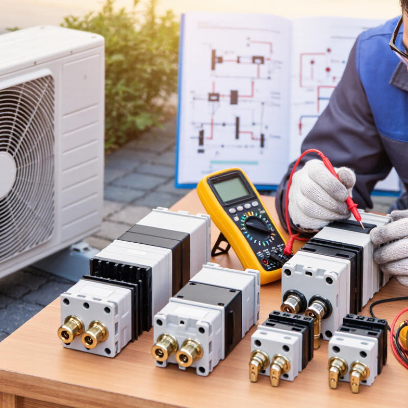
An air conditioner contactor is the electrical switch between the control circuit and the compressor or fan motor. It allows a low-voltage thermostat signal to control higher operating current safely. When cooling starts, the contactor coil energizes and pulls the contacts together. Power then reaches the outdoor unit. That separation protects delicate controls from motor current. A sharp click is normal. Buzzing is not.
Choosing the right contactor starts with system data, not cabinet appearance. Check the coil voltage, number of poles, load rating, and motor requirements. The coil must match the control voltage, such as 24 volts. The contacts must handle both running current and starting demand. RLA and LRA values provide useful guidance. A two-pole contactor may suit one system, while another requires three poles. Always verify the wiring diagram.
Field inspections often reveal pitted contacts, darkened terminals, or melted insulation. These signs indicate heat, poor connections, or excessive cycling. A visual match can mislead. I have learned that replacing only the contactor may hide a deeper problem, such as a failing capacitor or locked compressor. Measure voltage and current before installation. Check that the replacement fits firmly and leaves no loose wires. Even experienced technicians can miss a weak coil. A qualified inspection remains important when symptoms are unclear.
| Selection Dimension | Typical Options | What to Check | Selection Guidance |
|---|---|---|---|
| System voltage | 24 V, 120 V, 208–240 V, or 277 V AC control circuits | Read the voltage printed on the control transformer or wiring diagram. | The contactor coil voltage must match the actual control-circuit voltage. A 24 V coil is common in comfort-cooling equipment, but it should never be assumed. |
| Number of poles | 1, 2, or 3 power poles | Count the conductors that must be switched and confirm local code requirements. | Single-phase outdoor units commonly use 2-pole switching. Three-phase equipment generally requires 3 poles. Do not use an undersized or incorrectly configured pole arrangement. |
| Load current | Contactor ratings commonly range from about 20 A to 60 A in comfort-cooling equipment | Compare the contactor rating with the compressor and fan motor nameplate data, including RLA and FLA. | Select a rating equal to or greater than the required load under the applicable utilization category. The largest current rating alone does not guarantee suitability. |
| Utilization category | AC-1, AC-3, or manufacturer-specific motor/compressor ratings | Check whether the published rating covers hermetic refrigeration compressors or motor starting duty. | Compressor starting current is much higher than running current. Use the correct compressor or motor-duty rating rather than relying only on a resistive AC-1 rating. |
| Coil frequency | 50 Hz, 60 Hz, or 50/60 Hz | Verify the frequency shown on the replacement coil and equipment documentation. | A coil designed for the wrong frequency can overheat, chatter, or fail to pull in correctly. Use a 50/60 Hz coil only when its marking permits both frequencies. |
| Auxiliary contacts | None, 1 normally open, 1 normally closed, or convertible auxiliary contacts | Inspect the control schematic for crankcase heaters, alarms, interlocks, or status feedback. | Choose auxiliary contacts only when the circuit requires them. Confirm their contact arrangement and current rating separately from the main power poles. |
| Short-circuit withstand | SCCR values vary by assembly and protective device | Compare the equipment SCCR with the upstream fuse or circuit-breaker protection. | The contactor and its specified overcurrent protective device must be suitable for the available fault current. Do not infer SCCR from the ampere rating alone. |
| Enclosure and environment | Open, enclosed, indoor, outdoor, dusty, or humid installations | Consider ambient temperature, moisture, vibration, contamination, and available enclosure space. | Use an enclosure or environmental protection suitable for the installation. Outdoor equipment may require additional protection against moisture and corrosion. |
| Terminal configuration | Screw, box-lug, spring, or quick-connect terminals | Check conductor size, terminal capacity, tightening torque, and required wire type. | The terminals must accept the installed conductors and be tightened to the specified torque. Loose connections can cause overheating and contact damage. |
| Physical fit | Compact, standard, or heavy-duty mounting formats | Measure mounting-hole spacing, height, depth, terminal position, and clearance. | A replacement should fit securely without forcing wires or reducing required electrical clearances. |
| Operating temperature | Ambient limits commonly include approximately −20 °C to +55 °C, depending on construction | Use the temperature range stated for the specific contactor and application. | High ambient temperature reduces thermal margin. Derating may be required when the contactor is installed in a hot or enclosed space. |
| Expected switching duty | Occasional cycling, frequent cycling, or high-cycle control | Estimate starts per hour and total operating cycles over the equipment life. | Frequent compressor cycling can shorten contact life and may indicate a control or system problem. Select a contactor with an appropriate mechanical and electrical life rating. |