Empowering Engineering Excellence: Innovate, Elevate, Deliver.

What Are Moulding Components Used For?

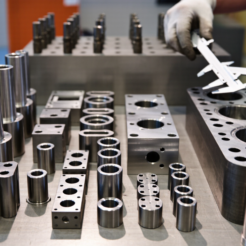
Moulding Components are essential parts used to shape, support, and finish products during manufacturing. They appear in injection moulds, die-casting systems, compression tools, and precision assembly equipment. Typical examples include mould bases, inserts, cores, cavities, guide pillars, bushes, ejector pins, and cooling channels. Each part has a specific function. Together, they control dimensions, surface quality, production speed, and component release.

In practical production, engineers select Moulding Components according to material behavior, pressure, temperature, and expected cycle life. A hardened steel insert may resist repeated abrasion, while a carefully positioned cooling channel can reduce warping. Ejector pins must remove a formed part without leaving deep marks. Small alignment errors can create flash, uneven walls, or costly downtime. A small detail matters.

Reliable component selection also depends on maintenance experience. Operators inspect wear patterns, lubrication points, venting areas, and damaged edges during scheduled checks. They may compare a finished part with technical drawings and inspection data before approving a tool. This approach connects design knowledge with real manufacturing evidence. However, no component choice is perfect for every application. A solution that works for a short production run may fail under continuous use. Engineers must reconsider assumptions, test samples, and adjust tolerances when results differ from expectations. Understanding what these components do helps manufacturers improve reliability, reduce waste, and build safer, more consistent production processes. Their value is practical, measurable, and often visible in the smallest surface detail.
What Are Moulding Components Used For?

Classify Moulding Components by Function Under ISO 20457 Tolerance Practice

Moulding components create, control, and release a plastic part during production. Their functions should be classified before tolerances are assigned. Forming components include cavities, cores, slides, and inserts. They define surfaces, holes, ribs, and parting lines. Guiding components keep moving mould halves aligned under repeated closing forces. Ejector pins, sleeves, and plates remove the cooled part without damaging delicate edges. Cooling channels manage heat near thick bosses and uneven wall sections. Venting features allow trapped air and gases to escape.

ISO 20457 provides a practical tolerance framework for moulded plastic parts and their acceptance conditions. It helps engineers distinguish between dimensions controlled by the mould and dimensions affected by material shrinkage. A locating feature may need tighter control than a cosmetic surface. A sealing diameter deserves closer attention than a hidden rib. Engineers should record the selected tolerance class, material condition, measurement method, and inspection temperature. Small details matter.

On the shop floor, I have seen good mould designs fail because every dimension received the same tolerance. That approach looks tidy, but it ignores function. It also increases machining and inspection effort. ISO 20457 should guide decisions, not replace them. Resin behaviour, mould wear, cooling balance, and ejection marks still require review. Some classifications remain debatable. A vent may serve both forming and gas-release functions, so its critical tolerance needs careful agreement between design and production teams.

What Are Moulding Components Used For?

Moulding components are classified below by their primary function in a moulding system. The chart counts representative component types used in conventional injection moulds; ISO 20457:2018 defines tolerances and acceptance conditions for plastics moulded parts rather than prescribing a fixed component classification.

Part-forming components create the moulded geometry. Guidance, ejection, feed, thermal-control, and support components enable accurate closing, filling, cooling, release, and operation of the mould. Dimensional requirements should be specified and verified in line with the applicable ISO 20457 tolerance practice for the finished moulded part.

Use Core, Cavity, and Inserts to Form Geometry and Surface Finish

What Are Moulding Components Used For?

Use Core, Cavity, and Inserts to Form Geometry and Surface Finish

Moulding components translate a part drawing into controlled plastic geometry. The core shapes internal features, such as holes, ribs, and bosses. The cavity creates the external profile. Together, they define wall thickness, draft, parting lines, and the visual character of the finished part.

According to Grand View Research’s Injection Molded Plastics Market report, the market was valued at approximately 284 billion US dollars in 2022. PlasticsEurope reported global plastics production of about 400 million tonnes in 2022. These figures suggest why repeatable tooling matters. Small errors in a core or cavity can affect thousands of moulded parts. That assumption is risky.

Inserts handle local details without replacing the entire moulding block. Engineers use them for deep pockets, fine lettering, replaceable wear areas, and difficult cooling zones. A hardened insert can also support a sharper edge or a cleaner texture. Surface finish depends on more than polishing. Machining marks, electrical discharge machining, steel hardness, venting, and cooling all leave evidence on the part. A glossy cavity may create a bright outer surface, while a textured insert can hide flow marks or reduce glare. It can also expose poor filling.

Practical inspection should compare the tool surface with the approved part standard. Measure roughness where appearance matters. Check edges under direct light. Not every defect comes from the mould. Process settings still matter.

What Are Moulding Components Used For? - Use Core, Cavity, and Inserts to Form Geometry and Surface Finish

Moulding Component Primary Function Geometry Formed Surface-Finish Contribution Common Material Choices Typical Design Considerations
Core Forms the internal side of a moulded part and occupies the negative space inside the product. Internal walls, holes, ribs, bosses, channels, and other recessed features. Transfers its machined, polished, textured, or coated surface to the inside of the part. Pre-hardened tool steel, hardened tool steel, stainless tool steel, or aluminium for lower-volume tooling. Must allow adequate draft, support cooling requirements, resist wear, and maintain alignment with the cavity.
Cavity Forms the external side of a moulded part and defines the outside envelope. Outer contours, raised features, decorative details, logos, and visible part surfaces. Usually determines the appearance of the visible surface, including gloss, texture, and pattern definition. Tool steel for production moulds; aluminium may be used for prototypes or shorter production runs. Requires careful control of polish, texture, parting lines, venting, cooling, and shrinkage allowance.
Replaceable Insert Creates a removable section within the core or cavity for a local feature or a high-wear area. Small pockets, ribs, lettering, holes, undercuts, shut-offs, and complex local details. Allows a specific area to receive a different polish, texture, coating, or repair treatment. Hardened tool steel, stainless steel, copper alloys for thermal performance, or wear-resistant tool materials. Should be accurately located, securely retained, easy to remove, and designed to avoid visible mismatch lines.
Interchangeable Insert Permits selected geometry to be changed without manufacturing an entirely new mould base. Product variants, cavity identification features, alternative logos, and model-specific details. Supports consistent finishing across product versions while allowing individual inserts to be refinished or replaced. Pre-hardened or hardened tool steel, selected according to production volume, wear, and surface requirements. Interface dimensions and datum locations must be repeatable to prevent steps, gaps, or mismatch at the part surface.
Slide or Side Core Forms features that cannot be released directly along the main mould-opening direction. Side holes, transverse slots, hooks, snap features, and undercut geometry. Maintains the required finish on side surfaces while controlling witness marks at the sliding interface. Hardened tool steel or wear-resistant steels, often with treated sliding surfaces. Needs reliable guidance, lubrication, wear control, correct shut-off angles, and sufficient clearance for movement.
Texture or Pattern Insert Applies a controlled decorative or functional pattern to a selected mould surface. Grain patterns, fine textures, grip areas, matt zones, and visual contrast features. Directly establishes the replicated texture; the final result also depends on mould temperature, filling, and material behaviour. Tool steel or stainless tool steel with chemically etched, laser-textured, blasted, or chemically treated surfaces. Texture depth, draft angle, cleaning access, and alignment must be controlled to prevent distortion or gloss variation.
Cooling Insert Improves heat removal near thick sections, deep cores, or geometrically difficult areas. Does not normally define visible geometry; it supports the moulding of surrounding features. Helps reduce uneven cooling, sink marks, warpage, and local gloss differences when properly designed. Tool steel, copper alloys, or other thermally conductive mould materials selected for the application. Channel location, sealing, corrosion resistance, pressure capability, and cleanability are important factors.

Note: The core and cavity work together to create the moulded part. Inserts are used to manage complex features, product variations, local wear, maintenance, and surface-finish requirements.

Use Ejector, Guide, and Clamping Parts for Release and Alignment

What Are Moulding Components Used For?

Use Ejector, Guide, and Clamping Parts for Release and Alignment

Moulding components help a tool open, align, and release finished parts safely. Ejector pins push the moulded piece from the cavity after cooling. Their positions must match strong areas of the part. Otherwise, they may leave white marks, dents, or uneven pressure. A smooth release matters.

Guide pins and guide bushes keep the mould halves aligned during every closing cycle. They protect the cavity and core from unwanted contact. Even a small alignment error can damage edges or create inconsistent wall thickness. Technicians should check guide surfaces for scoring, dirt, and unusual wear. Clean contact surfaces support repeatable production.

Clamping parts hold the mould securely against machine pressure. They distribute force through plates, bolts, and supporting points. Correct clamping prevents flash along the parting line. It also reduces movement during injection. In my experience, the first setup is rarely perfect. A clamp may feel tight but still load the tool unevenly. Measuring plate contact and checking bolt torque can reveal this problem. Do not guess.

Material choice also affects service life. Hardened steel suits repeated movement, while corrosion-resistant options help in humid workshops. Lubrication must follow the component maker’s instructions. Too much lubricant can attract dust and affect moulded surfaces. Small details matter. Regular inspection keeps release and alignment predictable.

Use Cooling Channels for Heat Control; Cooling Is Often 60–70% of Cycle Time

What Are Moulding Components Used For?

Moulding components shape, support, cool, and release a plastic part. They include cavities, cores, ejector pins, guide systems, and cooling channels. Among these parts, cooling channels often control the production rhythm. Industry technical proceedings from the Society of Plastics Engineers estimate that cooling can consume 60–70% of an injection moulding cycle. That figure is not universal. Material grade, wall thickness, mould steel, and part geometry can change it significantly.

Cooling channels remove heat from the cavity and core before ejection. Poor channel placement creates hot spots, sink marks, warpage, and longer cycle times. A practical design keeps channels close to the moulding surface without weakening the steel. Engineers also check flow balance, pressure loss, and coolant temperature.

A 2022 manufacturing energy report from the U.S. Department of Energy identified process cooling as a major industrial energy load, reinforcing the value of efficient heat transfer. Small details matter. A blocked passage can quietly increase cycle time.

In production, technicians should measure inlet and outlet temperatures, not rely only on machine settings. Infrared checks can reveal uneven cooling across a large mould.

I have seen apparently minor temperature differences produce visible distortion. The 60–70% estimate is useful, but it should be tested against actual cycle data. Sometimes the design is the problem.

Use Hot Runners and Gate Systems to Reduce Runner Waste Toward Zero

What Are Moulding Components Used For?

Use Hot Runners and Gate Systems to Reduce Runner Waste Toward Zero

Moulding components guide, fill, cool, and release plastic parts with controlled repeatability. Hot runners keep molten material warm inside the manifold and nozzles. Gate systems then deliver the melt close to each cavity. This layout can remove most cold runners from the finished process.

The benefit appears beside the machine. Instead of trimming a solid runner from every shot, production sends more plastic into useful parts. A well-balanced system can reduce scrap, shorten regrind handling, and support steadier cycle times. Engineers still need to check gate location, cavity pressure, cooling, and material sensitivity. Small errors can create burn marks, weld lines, or uneven filling.

Near-zero runner waste is a target, not a promise. Some moulds need purge material, start-up shots, or protective processing steps. These losses should be measured, not ignored. A practical review compares material input, accepted parts, rejected parts, and maintenance waste. Operators can also inspect nozzle temperatures and gate seals during each shift. One blocked gate can quietly increase pressure and spoil several cavities. Hot runners help greatly. They do not replace sound mould design, accurate temperature control, or disciplined maintenance.

Download
Brochure